Лазерные атмосферные системы связи
Оборудование для БПЛА
Беспилотные летательные аппараты
Оптоэлектронный генератор.
Новороссия
оптоэлектронный генератор ОЭГ СВЧ
Патенты2
шлемы
машина времени
Антенны - активные фазированные решетки
5.8G 14DBi high gain Mini Panel Antenna SMA/RP-SMA
5.8G 14dBi High Gain Мини панельная антенна SMA / RP-SMA
Частотный диапазон МГц: 5600-5950 МГц
Gain-дБи: 14dBi
3db Вертикальная Ширина луча: 40 градусов
3db Горизонтальная Ширина луча: 35degree
Impedance-: 50 Ом
Поляризация: Вертикальная
Подавление боковых лепестков> = 13dB
КСВ: <= 1,5
Соотношение вперед-назад;> = 25 дБ
Максимальная мощность, Вт: 50
Разъем: RP-SMA-внутреннее отверстие / SMA внутренний штифт (опционально)
Размеры мм: 60X55X6
Вес: 30 г
DC Заземление
Высокая информативность функция восстановления.


Активные фазированные решетки
http://www.radartutorial.eu/06.antennas/Phased%20Array%20Antenna.en.html
Phased Array Antenna 
Figure 1: left: two antenna elements, fed with the same phase, right: two antenna elements, fed with different phase shift A phased array antenna is composed of lots of radiating elements each with a phase shifter. Beams are formed by shifting the phase of the signal emitted from each radiating element, to provide constructive/destructive interference so as to steer the beams in the desired direction. 
Figure 2: Animation of the electronic beam-deflection In the figure 1 (right), the signal is emitted by the upper radiating element with a phase shift of 22 degrees later than of the lower radiating element. Because of this the main direction of the emitted sum-signal is moved slightly upwards. (Note: Radiating elements have been used without reflector in the figure. Therefore the back lobe of the shown antenna diagrams is just as large as the main lobe.) The main beam always points in the direction of the increasing phase shift. Well, if the signal to be radiated is delivered through an electronic phase shifter giving a continuous phase shift then the beam direction will be electronically adjustable. However, this cannot be extended unlimitedly. The highest value, which can be achieved for the Field of View (FOV) of a olanar phased array antenna is 120° (60° left and 60° right). With the sine theorem the necessary phase moving can be calculated. The following figure graphically shows the matrix of radiating elements. Arbitrary antenna constructions can be used as a spotlight in an antenna field. For a phased array antenna is decisive that the single radiating elements are steered for with a regular phase moving and the main direction of the beam therefore is changed. E.g. the antenna of the RRP 117 consists of 1584 radiating elements arranged in an analogue beamforming architecture. More sophsticated radar sets use the benefits of a Digital Beamforming architecture.
Possible ArrangementsLinear Arrays
Figure 3: linear array of a phased-array antenna These antennae consist of lines whose elements are fed about a common phase shifter. A number of vertically about each other mounted linear arrays form a flat antenna.
This kind of the phased-array antenna is commonly used, if the beam-deflection is required in a single plane only because a turn of the complete antenna is anyway carried out ( RRP-117). 
Figure 4: planar array of a phased-array antenna Planar ArraysThese antenna arrays completely consist of singles radiating elements and each of it gets an own phase shifter. The elements are ordered in a matrix array. The planar arrangement of all elements forms the complete phased-array antenna.

Figure 5: frequency scanning array Frequency Scanning ArrayFrequency scanning is a special case of the phased array antenna where the main beam steering occurs by the frequency scanning of the exciter. The beam stearing is a function of the transmitted frequency. This type of antenna is called a frequency scanning array. The normal arrangement is to feed the different radiating elements from one folded waveguide. The frequency scanning array is a special case of serial feeding type of a phased array antenna and is based on a particular property of wave propagation in waveguides. The phase difference between two radiating elements is n·360° at the normal frequency. By changing the frequency, the angle Θs between the axis of the main beam and the normal on the array antenna changes. Height information is generated using the following philosophy:
As frequency is varied, the beam axis will change, and scanning can be accomplished in elevation. The radar set is designed so that it keeps track of the frequencies as they are transmitted and then detects and converts the returned frequencies into 3D display data. Note that frequency scanning reduces the value of using frequency change as a means of achieving other valuable effects (benefits of pulse compression). Phase-increment CalculatingThe phase shift Δφ between two successive elements is constant and is called phase-increment. How large is this phase shift to reach a certain value of the beam steering? A linear arrangement by isotropic radiating elements is looked at. 
Figure 6: grafic derivation of the formula
We start with the calculation of the phase-increment. A part of this phase shift is realized by the delay in the feeding line yet. |
|||||||||||||||||||||||||||
 The phased array demonstrator is a simple training device, designed to use in a classroom. With the help of this device can be demonstrated practically how a phased-array antenna works. An oscillator transmits with less power over a group of four Yagi antennas in free space in a free ISM frequency band (Industrial, Scientific and Medical band). Here was chosen a frequency between 2.40 – 2.48 GHz. The resultant power flux density from the antennas in the space can be measured by a commercially available high-frequency analyzer. The direction of maximum radiation can be thus determined. An electronic phase shifter which is controlled by a static voltage may change the phase of each individual radiator to 45, 90, or 135 degrees. In total, this results in swiveling the direction of the radiations maximum by about 16 degrees to the left or (the other switch position) to the right. The far field of the antenna starts at a distance of about 3 to 4 m. Here the to measured radiation is very weak yet, and it is measured in microwatts per square meter. Incidentally it may be pointed out that the by the analyzer received power decreases with the square of the distance (Free-space path loss). If a direction with maximum power density was found, so the direction of the radiation can be changed using a changeover switch, so that the instrument cannot indicate any value. The commercial high-frequency analyzer uses a very broadband calibrated antenna. With this antenna can be measured the radiation caused by the mobile phones of the students too. In order to prevent this falsifying the measuring result by interference, a narrow-band Yagi antenna with high directivity has been developed for this instrument. However, this additional measurement antenna is not calibrated. Therefore the displayed by the meter values can be compared only as relative values with each other. This specialized training device has been developed by Radartutorial. The construction and distribution is performed by Köster Systemtechnik (Germany). |
|||||||||||||||||||||||||||
 |
|||||||||||||||||||||||||||
|
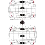
This antenna form (named after one of its Japanese inventors, Professor Yagi) has especially been developed for short wave up to the UHF-band. Yagi- antennas are very popular because their simplicity and relative high gain and are commonly referred to as beam antennas. They are used also in radar sets however. Yagi-antennas use mutual coupling between standing-wave current elements to produce a traveling-wave unidirectional pattern. It consist of an array of a dipole and additional closely coupled parasitic elements. The elements in the Yagi antenna are usually welded to a conducting rod or tube at their centers. This support does not interfere with the operation of the antenna. Since the driven element is center-fed, it is not welded to the supporting rod. The center impedance can be increased by using a folded dipole as the driven element. The various elements are indicated in the figure. The spacings between the elements are not uniform. The only element of the structure that is excited is the dipole. All other parasitic elements are closely coupled by radiation. The radiation from the different elements arrives in phase in the forward direction, but out of phase by various amounts in the opposite directions. The bandwidth of a Yagi-Uda antennaa is determined by the length, diameter and spacing of the elements. For most designs bandwidth is typically only a few percent of the design frequency. The Yagi antenna shown in the figure 1, has one reflector, one folded dipole as radiator and three directors. In general, the greater number of parasitic elements (directors and reflectors) used, the greater the gain. However, a greater number of such elements causes the array to have a narrower frequency response as well as a narrower beamwidth. Therefore, proper adjustment of the antenna is critical. The gain does not increase directly with the number of elements used. For example, a three-element Yagi array has a relative power gain of 5 to 6 dB. Adding another director results in a 2 dB increase. Additional directors have less and less effect. |
|||||||||||||||||||||||||||
 |
|||||||||||||||||||||||||||
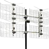
 Figure 5: Radar using group of Yagi-antennae, (P-18 “Spoon Rest D”) antenna gain G = 69 Figure 5: Radar using group of Yagi-antennae, (P-18 “Spoon Rest D”) antenna gain G = 69 |
|||||||||||||||||||||||||||
 
|
|||||||||||||||||||||||||||
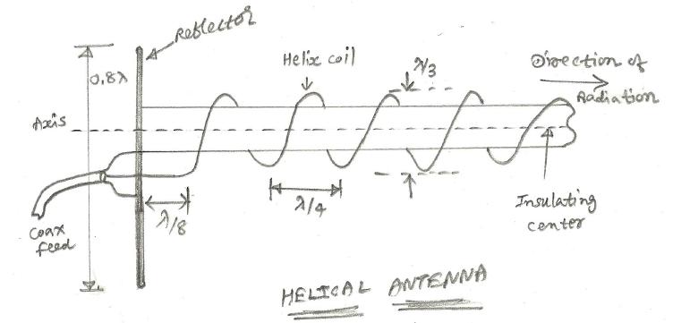
Helical Antenna More
www.rfwireless-world.com |
|||||||||||||||||||||||||||
Horn Antenna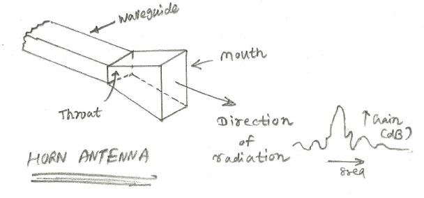
Horn antenna is regarded as flared waveguide. It can work more efficiently along with parabolic reflector as found in dish antenna. Horn antenna is used in satellite/microwave applications. Normal waveguide if used for transmission of E-M waves it will not tightly coupled with free space impedance and results in reflected power and standing waves. The mismatches are avoided by flaring the end of waveguide which creates horn antenna. The more gradual the flare, better is the matching and lesser the losses. This results in greater gain and directivity. Depending upon the flaring there are different types of horn antennas viz. sectoral horn,pyramidal horn and conical horn. Gain of the pyramidal horn is summarized below. Hor. beamwidth of the pyramidal horn is summarized below. Parabolic Reflector Antenna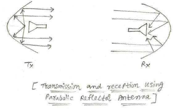
This parabolic reflector antenna is used in conjunction with horn antenna as shown in the figure. It is made of metal or screen mesh. As shown in the figure, during transmission EM-waves fall on to the wide dish and gets radiated into the air, while during reception EM- waves fall on to the dish and gets focused to the horn antenna. Aperture of the parabola antenna is the area of outer circle of the parabola. Helical Antenna
As the name suggests helical antenna is made of coil surrounding the insulating support. Diameter of the wire is about 1/3 of wavelength and spacing between turns is about 1/4 of wavelength. About 6-8 turns are usuallu used in this type of the antenna. Ground plane reflector behind helix of shape circular or square is used. This antenna is widely used in VHF/UHF range. Gain and beamwidth of this helical antenna is about 12-20 dB and 12-45 degree respectively. Slot AntennaIt is formed by cutting the metal sheet or waveguide about half wavelength in size. Due to this cutting of the slot it is known as slot antenna. Several slots can also be cut to form slot antenna array. Array antenna usually will have better gain and directivity compare to single slot antenna. Slot antennas are widely used in high speed aircraft by filling the slot with insulating material to create smooth surface. Other external antennas will not be convenient to use at such high speed of the aircraft. Dielectric AntennaThey are made of polystyrene or using plastic or other dielectric materials. These lens antennas are used for millimeter wave frequency above 40 GHz. In this kind of antenna dielectric lens is placed over end of the horn antenna which focuses waves into narrower beam. This results in greater gain as well as directivity. Microstrip Patch Antenna
This type of antenna is made with microstrip based design on PCB.Hence it is called as microstrip patch antenna. This antenna is basically circular or rectangular area of copper separated by conducting ground plane. Between this there will be insulating surface. In the case of rectangular antenna, width is approx. 1/2 of wavelength while in the case of circular antenna, diameter is approx. 0.55 to 0.59 of wavelength. Phased Array AntennaPhased array antenna is developed using multiple antennas on a common PCB or plane. The antennas used here are patch antennas or dipole antennas in a array. This combination of multiple antennas help improve gain as well as directivity. Individually all the antennas of the array are controlled and hence EM waves can be radiated in the different directions as desired. The same concept is applied in YAGI antenna and parabolic dish antenna used for TV reception. The other application of this type of antenna is radar/satellite based communication systems. There are two types of arrangement designed in this type of antenna. In one of this type of configuration, all the antennas are fed from common transmitter or receiver. In the other type of configuration, low power transmitter amplifier or LNA is used with each of the array antennas. Dipole Antenna
Antennas radiate effectively when length of antenna is directly related to transmitted signal wavelength.Dipole antennas are available in half wave or quarter wavelength in sizes. Half wave dipole antenna called as doublet will have length equal to 1/2 of wavelength of operating frequency. Usually RG-59/U is used for 73 Ohm coax line and RG-11/U is used for 75 Ohm line. Length of this dipole, L = 468/Freq Directional AntennaAntenna having omnidirectional radiation pattern transmit/receive in any direction. In order to send and receive in particular direction requires antenna with high directivity. This type of antenna having radiation pattern limited to narrow horizontal range is called directional antenna. In order to design this kind of antenna two or more antennas are combined which make an array. This increases gain and directivity. There are two antenna array types viz. parasitic arrays and driven arrays. Folded Dipole Antenna
This type of antenna is popular due to its impedance which is about 300 Ohm. The folded dipole antenna is made of 300 Ohm twin lead having length equal to one half wavelength. Their ends are soldered. This is variation of the standard half wavelength dipole antenna. As shown in the figure, two parallel conductors are connected at the ends, with one side open at the center. This central open part is interfaced wih transmission line. Spacing between conductors is inverse proportional to frequency. For low frequency application, spacing is about 2 or 3 in. For high frequency application,spacing is about 1 in. Ground Plane Antenna
When vertical polarization and omni directional pattern is needed, ground plane antenna can also be replacement to standard half-wave dipole antenna. This antenna is fed with coaxial cable. It is formed by center conductor connected to the the vertical radiator and shield connected to the earth ground. This generates vertical omnidiractional radiation pattern. The vertical ground plane antennas are widely used in cars,trucks,boats and other vehicles. The flat metallic surface of the vehicle acts as superior ground plane for VHF/UHF antennas. The impedance of this vertical ground plane antenna is about 36.5 Ohm. As no coaxial cable exists at this impedance, standard 50 Ohm cable is used which generates mismatch of about 1.39 SWR. YAGI AntennaYAGI antennas were widely used for TV reception, but as they are designed for one frequency only, they are not suited for wide frequency range. YAGI antennas are made of one driven element, one reflector and one or more directors. They are made with aluminium tubes and aluminium cross member. Log Periodic Antenna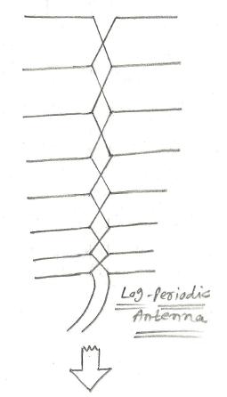
The benefit of this log periodic antenna is its wide bandwidth application. It is formed by different length driven elements. The longest and shortest elements are of half wavelength long at lowest and highest frequency of interest. The elements of this log periodic antenna are fed with transmission line segments. The phases of the signals sent to different elements are properly set to achieve high directivity and the best gain. |
|||||||||||||||||||||||||||
 |

Antenna's Direct C4-CJM 20-Inch ClearStream 4 Extreme Range UHF Outdoor Antenna Mount